The oscillating circuit, Tuning or resonant circuit in the wireless radio receivers
An oscillating circuit is electric circuit in which there is the interchange of the energy stored in the induction coil as a magnetic field and the capacitor as an electric field, The oscillating circuit consists of an induction coil of very small resistance, capacitor, battery and they are connected through switches a and b.
How oscillating circuit works
When the switch (a) is turned on: A momentary current passes from the battery to charge up the capacitor such that the plate connected to the positive pole becomes positively charged while the plate connected to the negative pole becomes negatively charged.
The current stops flowing when the potential difference between the two plates of the capacitor equals the potential difference of the battery, An electric field is built up between the capacitor plates where energy is stored as an electric field.
When switch (a) is turned off and switch (b) is turned on: The capacitor discharges its charge through the inductive coil and therefore a momentarily current passes from the positive plate to the negative plate, which decreases the voltage across the capacitor till it collapses and the electric field between its plates vanishes.
The flowing current through the coil generates a magnetic field that stores the energy that was stored in the capacitor before, as electric energy, Initially, there is a high current flowing through the coil due to the high voltage across the capacitor plates.
As this current fades gradually, a forward current is induced in the coil by self-induction that draws more charges from the positive plate of the capacitor towards the negative plate.
Consequently, the plate that was negatively charged becomes positively charged while the other plate becomes negatively charged reversing the capacitor polarity and generating an electric field between them.
The current through the coil ceases and so is the magnetic field till they vanish, Accordingly the energy stored in the coil as a magnetic field is transformed into electric energy stored in the capacitor.
Next that, the capacitor is charged another time through the coil in a direction opposite to the original charge, Thus the charging and discharging of the capacitor is cycled and an electric oscillation of high frequency is produced in the circuit, interchanging the energy alternately between the two fields.
The process of charging and discharging in the oscillating circuit stops after a while, due to the ohmic resistance of the coil and the other circuit wires, a part of the energy is dissipated as heat energy, This results in a gradual decrease in the alternating current in the circuit and the voltage across the capacitor plates, as well, This hinders charging and discharging process causes the current eventually to die away to zero.
However, if this loss is compensated by extra charges supplied to the capacitor, the oscillatory action of passing energy back and forward between the capacitor and inductor will continue indefinitely.
The relation between the frequency, XL, XC, R and Z
The ohmic resistance does not change as the current frequency changes, The inductive reactance increases as the AC frequency increases (XL∝ f), The capacitive reactance decreases as the AC frequency increases (XC∝ 1/f), The impedance Z of the circuit decreases till it becomes minimum value when XL = XC which called a state of resonance, After that the impedance Z of the circuit increases as the AC frequency increases.
Tuning or resonant circuit
Tuning or resonant circuit is used in Tuning radio receivers for picking up the signal of a particular station, at a particular frequency, Tuning or resonant circuit consists of:
- A capacitor of variable capacitance.
- Induction coil whose inductance can be altered.
- AC supply of variable frequency.
- Hot wire ammeter.
How it works
When the frequency of the AC supply is varied, the flow of the current intensity varies such that the current value decreases as the difference between the frequency of the power supply and the resonance frequency increases, The current value increases as the frequency of the power supply approaches the resonance frequency.
The current value reaches its maximum when the frequency of the supply equals the resonance frequency of the circuit (when the inductive reactance equals the capacitive reactance) and the circuit is said to be resonant.
Deduction of the resonant frequency
In the oscillating circuit when capacitive reactance and inductive reactance are equal they cancel out each other, leaving only the resistance of the circuit to oppose the flow of current, thus the current reaches its maximum in that circuit.
The circuit frequency (f) can be deduced as follows:
XL = XC
2πfL = 1/2πfC
f ² =1 / 4 π² L C
Taking the square root for the two sides
f = 1 / 2 π ( L C )½
Where: (C) is the capacitance of the capacitor, (L) is the coefficient of self-inductance of the coil.
Factors affecting the resonant frequency
- The square root of the self-inductance coefficient of a coil, (inversely proportional).
- The square root of the capacitance of the capacitor, (inversely proportional).
Resonating the circuit frequency with the source frequency can be achieved either by tuning (varying) the source frequency, the capacitance or the coil inductance, Resonance in the tuned circuit and in sounds are alike, Intensity of the sound strengthens when two tuning forks vibrate at the same frequency and weakens when their frequencies differ markedly.
Conclusion: If multiple frequencies of different electric sources affect an oscillating circuit at the same time, the circuit does not allow current to pass except that having frequency either equal or so close to the circuit frequency.
The tuning (resonant) circuit is an oscillatory circuit that contains a resistor, induction coil, capacitor & AC source and does not allow to flow a current except that has the same frequency as its or so close to it.
When the circuit is resonant:
- The supply frequency equals that of the circuit.
- The maximum value of effective current passes in the circuit.
- The voltage across the coil (VL) = The voltage across the capacitor (VC) and hence the voltage across the resistor = emf of the AC supply.
- The inductive reactance (XL) = The capacitive reactance (XC) and they cancel each other.
- The circuit has the minimum impedance which is the ohmic resistance Z = R.
- The current is in phase with the total potential difference, so, the phase angle (θ) = zero.
In the case of comparing the frequency of two oscillating circuits:
f1 / f2 = ( L2 C2 / L1 C1 )½
When the same coil is in the two circuits, meaning ( L = L1 = L2 ) then:
f1 / f2 = ( C2 / C1 )½
When the same capacitor is in the two circuits , meaning ( C = C1 = C2 ) then:
f1 / f2 = ( L2 / L1 )½
Tuning resonant circuit in the wireless radio receivers
In the radio receiver, the tuning circuit is connected to the antenna that is hit by electromagnetic waves of different frequencies transmitted by different stations, These different frequencies are generated in the antenna currents having the same frequencies of their stations, Thus, the tuning circuit in the radio receiver allows only the current that has a frequency equal to that of the circuit to pass.
When you like to hear a certain broadcast station, you tune the frequency of the circuit either by altering the capacitor capacitance or the number of turns in the coil to allow only the current that its frequency resonates with the circuit frequency.
This current then undergoes processes of amplification, and rectification, and finally the current that expresses the sound is separated to pass through a loudspeaker.
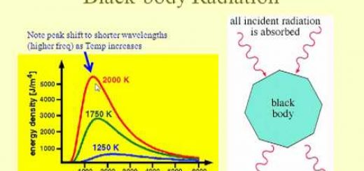
Quantum physics, Blackbody Radiation & importance of studying emitted rays from different bodies