AC circuit containing inductive coil of zero ohmic resistance or non inductive ohmic resistance
The inductive reactance is different from the ohmic resistance where the inductive reactance for a coil of zero resistance does not cause loss in electric energy, because the current resistance is due to the reverse induced emf where the electric energy is stored in the coil in the form of a magnetic field, The non-inductive ohmic resistance causes loss in electric energy in the form of heat energy.
AC circuits
The value of the self-inductance coefficient (L) for a solenoid coil is determined by the relation: L = μAN²/l, The electric current intensity passing in an induction coil of no resistance is determined from the relation:
I = Voltage difference at coil terminals (VL) / Inductive reactance of the coil (XL)
In high frequencies, the inductive reactance (XL) becomes very big where (XL∝ f), Consequently the electric current intensity decreases where (I ∝ 1/XL) and the circuit becomes as if it is opened.
AC circuit containing inductive coil of zero ohmic resistance
When connecting an inductive coil of zero ohmic resistance to an AC source and a switch in series, then on closing the circuit, the electric current grows gradually from zero to maximum value at a rate (ΔI/Δt).
The variation in the current intensity as time passes generates reverse induced emf by self-induction equals (− L ΔI/Δt), Where: L = self-induction coefficient of the coil.
The frequency of the induced emf is the same as that of the AC supply but acting in the opposite direction to the emf of the supply, So, the instantaneous value of the potential difference (V) = − L ΔI/Δt
The phase difference between the current and the potential difference
The electric current intensity (I) varies with the phase angle according to the sine curve as in the figure, the value (ΔI/Δt) represents the slope of the tangent drawn to the curve where:
- It reaches its peak value when the phase angle equals zero which means that the voltage (V) reaches maximum values.
- The slope decreases gradually to reach zero when (I) reaches its peak value and the voltage reaches zero.
- The slope (ΔI/Δt) becomes negative when the current intensity decreases and the voltage becomes a negative value.
So, the voltage (V) leads the current (I) by ¼ cycle or by a phase angle 90° due to the self-induction of the coil.
The inductive reactance in a coil (XL)
Since the reverse-induced emf produced by self-induction in a coil of zero resistance cause some kind of resistance to the flow of the original current, it is called inductive reactance, The inductive reactance in a coil (XL) is the opposition to the flow of the AC current through the coil due to its self-inductance.
The inductive reactance is measured in Ohm (Ω), The inductive reactance is determined from the relation: XL = 2πfL = ω L, Where: (L) coefficient of self-induction, (f) frequency of the current passing in the coil, (ω) the angular velocity.
When the inductive reactance of a coil = 100 Ω, It means that the opposition to the flow of the AC current through the coil due to its self-induction = 100 Ω.
Factors affecting the inductive reactance of a coil
- Current frequency (f), (directly proportional).
- Self-induction coefficient (L), directly proportional.
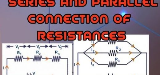
The inductive reactance of inductor network
When connecting many inductive coils together (away from each other) then, If conductors are connected in series.
L = L1 + L2 + L2
XL = ( XL )1 + ( XL )2 + ( XL )3
If the self-induction coefficients for all coils are equal and the number of coils (n).
L = n L1 , XL = n ( XL )1
If conductors are connected in parallel.
1/L = 1/L1 + 1/L2 + 1/L2
1/XL =1/( XL )1 + 1/( XL )2 + 1/( XL )3
If the self-induction coefficients for all coils are equal and the number of coils (n).
L = L1 / n , XL = ( XL )1 / n
AC circuit containing non inductive ohmic resistance
When connecting non-inductive ohmic resistance to AC source and a switch in series, then closing the circuit, the potential difference between the terminals of the resistance (R):
V = Vmax sin θ = Vmax sin ωt
Where: V = instantaneous value of potential difference, Vmax = maximum value of potential difference, θ = phase angle (θ = ωt), ω = the angular velocity (ω = 2πf).
Based on Ohm’s law, the electric current is determined from the relation:
I = V/R = Vmax sin ωt / R = Imax sin ωt
The potential difference and the current intensity in an ohmic resistance have the same phase, thus the current and potential grow together up to a maximum value and drop together to zero, The current and potential difference in resistance without induction are represented by two vectors having the same direction.
Properties of the alternating current, Hot wire ammeter uses, cons and pros